|
Build the "Rifficator" Another DIY project by M.J. Bauer |
||||
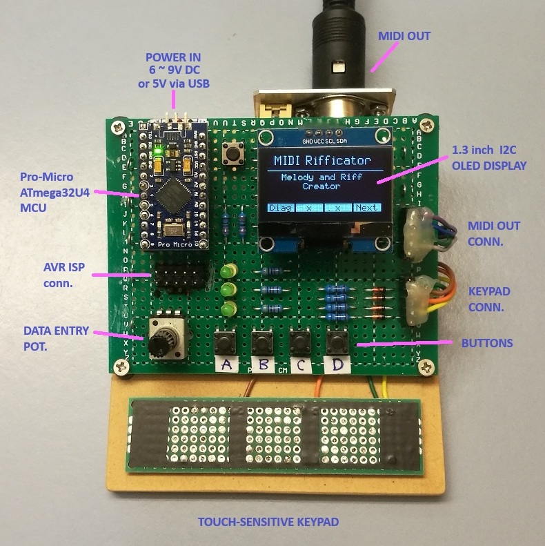 Photo: Rough prototype for "proof of concept". |
||||
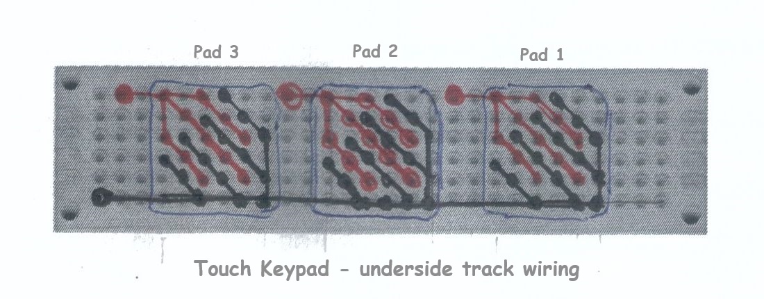
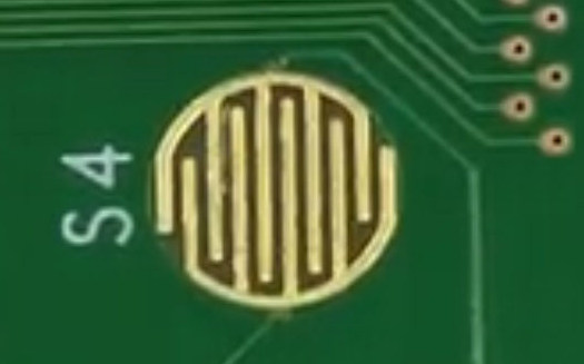
Since the beginnings of computer-generated music, countless attempts have been made to develop software to create interesting and musically appealing compositions. Some electronic music synthesizers and MIDI controllers provide a capability to generate random sequences of notes. So far, computer-generated music algorithms have not been very good at generating musically appealing compositions. While AI software such as ChatGPT can spew out pieces reminiscent of various musical styles, none of it sounds very original, innovative or inspiring (to me at least). And there's a good reason for that... AI compositions draw on a database of existing material put there by human "trainers". The Rifficator is a device intended to assist musicians to create melodies or "riffs". The idea is to allow the device to choose notes at random, guided by the user. Unlike some other computer-generated music software, the human operator dictates the rhythm, i.e. the timing of the notes. Also the sequence of notes is not pure random. A bunch of user-settable parameters determines which notes have priority, for example, only notes on a major scale, with variable probability of playing an accidental.Three keys (touch-pads or mechanical keys) are provided to trigger notes. Whether a new note in the sequence is lower-pitched, higher-pitched, or the same pitch as the previous note, is determined by which keys are pressed. Hitting the centre key alone selects a random note which may be lower or higher than the previous note. Hitting the left key usually selects a lower note than the previous note played. Hitting the right key alone usually selects a higher note. Hitting the centre key while either the left or right key is held pressed always results in the same note as the one previouly played. Output from the Rifficator is a MIDI sequence which can be fed into a synthesizer for playing and at the same time may be recorded using a computer app (MIDI sequencer, DAW, or whatever). Any desired part of the recorded sequence can then be edited and embellished, perhaps with a multi-track backing added. Here is the schematic of the prototype circuit board. 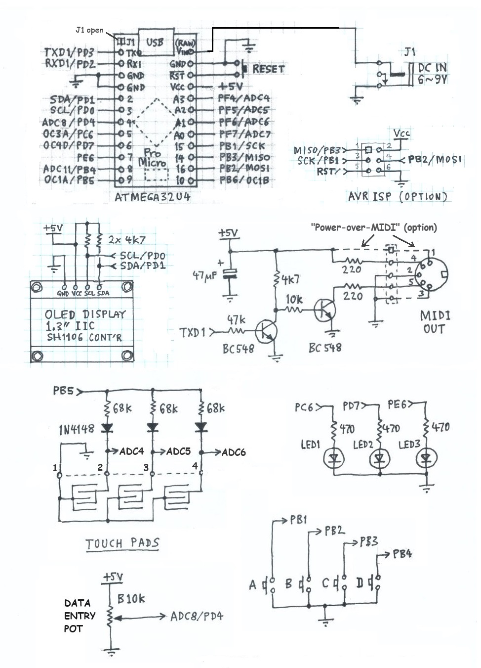 To simplify the circuit further, the 2 BC548 transistors forming the MIDI OUT buffer/driver may be omitted. The lower 220 ohm resistor can be connected directly to the MCU pin PD3/TXD1 (TXO). The green LEDs are also optional, but I found them useful while debugging the program code. The LEDs I chose were high-efficiency types... so bright that I had to increase the resistors to 47k to avoid being dazzled! In hindsight, I should have connected the (common) cathodes to a spare PWM output (PB6/OC1B) so that the brightness could be adjusted in the firmware. The USB socket broke off my Pro-Micro MCU module. This happens easily with those nasty little SMT micro USB connectors! No problem - USB is not necessary for this project. The board can be powered via the (RAW) VIN pin (6 to 9V), or by 5V into the Vcc pin (optionally from the MIDI OUT socket). An optional AVR ISP connector (DIP-6 pin header) allows the MCU to be programmed using an AVRISP mkII programming tool instead of the USB bootloader. Beware: Using ISP may erase the USB bootloader! The touch keypad was made from a piece of double-sided, thru-hole plated, dot-matrix proto board (aka "perf board"). Here's a sketch showing how wires are soldered to the underside. The red traces are signal lines; the black ones are GND lines. The image on the right is an example of a PCB touch-pad.
Assuming you are reasonably skilled in electronics prototyping, you now have enough information to begin construction of a Rifficator based on the above schematic. Firmware Download Rifficator firmware package A hex object file is included so you can program the device without needing to re-build the firmware. The board can be programmed via the USB port without needing Microchip/Atmel Studio (IDE) and without a hardware programming tool. Proceed as follows... The Pro Micro board has a flash-resident AVR bootloader. A Windows application called “AVRdude” communicates with the bootloader via USB to program firmware into the MCU flash memory. Hence you need to download some files to run "avrdude" on Windows. The best place to download the files is GitHub, here: https://github.com/mariusgreuel/avrdude/releases. There should be 3 distribution files: “avrdude.exe”, “avrdude.conf” and “avrdude.pdb”. Copy these files to a new folder named “AVRdude” on your PC local drive, in the “root directory” (C:\). Connect your board to a USB port on your PC. Open Windows “Device Manager” utility and click on “Ports (COM & LPT)”. Immediately after you apply power or reset the MCU, you should see the board’s USB-serial device listed. Note the number of the associated “COM” port. Be aware that the COM port number may change from time to time. Always check the allocated COM port after re-connecting the board to your PC. Copy the hex file "MIDI-Rifficator-v2.0.hex" (or latest update) into the folder "C:\AVRdude". If all goes well, avrdude will report success. To modify or extend the program... The firmware download package includes source code, libraries and all project files needed to build the program using Microchip/Atmel Studio IDE for AVR and SAM Devices. Download and install the app. Create a
project folder on your Windows PC local drive named "MIDI-Rifficator".
The "solution" file expects this name exactly. Copy all the files from
the distribution pack, "Rifficator-firmware-pack.ZIP" to your
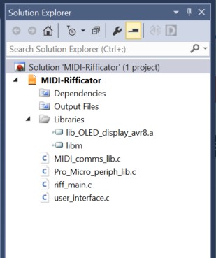
project folder. If Atmel Studio is already open, close it. Double-click the file "MIDI-Rifficator.atsln" in the project folder. Atmel Studio will open the "solution" (project). Check that all required "components" (files) are present and in the correct place, as can be verified in the "Solution Explorer" pane (screen-shot here)...
To view/edit a source file, click the file-name in the Solution Explorer pane. When you're done editing the source code, assuming everything is correct, click 'Build Solution'. If the build was successful, a hex object file "MIDI-Rifficator.hex" will be placed in the project sub-folder "..\Debug". To program the board, you have a choice between two options. Probably the easiest method is to proceed as above using AVRdude stand-alone from Windows Command Prompt. Another option is to create a "software programming tool" in Atmel Studio. This method allows you to program the board directly from within Atmel Studio. Proceed as instructed in the linked document, here... How to program the Pro-Micro board via USB using Atmel Studio IDE Additonal notes on Pro Micro USB bootloader variants Some Pro Micro boards have the Sparkfun (modified) bootloader installed. This behaves a little differently compared with the "normal" Arduino Micro/Leonardo bootloader. To enter bootloader mode (and remain in the bootloader) press RESET twice in quick succession. In case of the Arduino Micro/Leonardo bootloader (installed in some Pro Micro clones), the MCU enters bootloader mode immediately on power-up (and/or reset) and remains in bootloader mode for 10 seconds. After 10 seconds, the bootloader tries to start the user application program, if any. The bootloader must be running when AVRdude is started, of course. Please forgive me if I am stating the obvious, but I found it quite tricky to keep the bootloader running while at the same time starting AVRdude from within Atmel Studio. Persevere with it! Where to from here? At present, there is no "user manual" for the Rifficator. It should be fairly intuitive to operate. Fiddling with the user-settable parameters will give you some idea of what effect each one has on the random note generator. Parameters are stored in EEPROM, so they retain their values across power-downs, but be aware the parameters may default when the firmware is updated (depending on programming method). One
parameter in particular may need some explanation... 'Pr(accidental)'
is math shorthand for "probability of hitting an accidental". An
"accidental" in music is a note which is outside the diatonic scale.
For example, in the scale of C-major, all notes are "white" keys on the
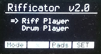
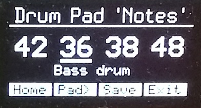
piano. Thus, any "black" note is an accidental. There are further improvements which I plan to implement in the note selection algorithm. Plus, the program will offer a choice of musical scales, including pentatonic. A future instalment of this blog will aim to give readers a better understanding of the internal workings of the program. In particular, the algorithms used to generate the random note numbers and the parameters that affect their behaviour will be explained in more detail. Meanwhile, reading the comments in the source code might give you some insight. ... Firmware update v2.0 (30-Sept-2024) This update lets you set the MIDI channel number (1..16). Select 'SET' (button D) from the Home screen and keep hitting 'Next' until you reach the 'MIDI Channel' screen (at the end of settable parameters). The MIDI channel is remembered only if you hit "Save" (button C) before you exit the screen. Version 2.0 has a new feature added... "Drum Player". The 3 (or 4) touch-pads are used to trigger drum sounds generated by any synth which supports General MIDI drum kit sounds. You need to select the MIDI 'Program' in your synth assigned to the GM 'Standard Drum Kit 1'. Note: The GM standard does not specifiy the MIDI Program Change number(s) assigned to drum kit(s). Refer to your synth user manual.
Each of the 3 (or 4) touch-pads can be assigned any of 26 drum sounds corresponding to MIDI 'note' numbers 36 to 61. Select 'Pads' (button C) from the Home screen. Use the control pot to change the note number of the drum (or other precussive) sound you want for pad #1 (left pad). Press 'Pad>' (button B) to view the drum number for pad #2 (centre). Ditto for pad #3 (and pad #4 where fitted). A cursor (underline) appears below the pad number to be changed with the pot. Any changes made to pad assignments are only temporary... Drum/pad numbers will revert to default values when the power is switched off... Except if you press 'Save' (button C)... then the new pad assignments will be remembered, i.e. saved in non-volatile memory (EEPROM). The Rifficator was designed originally to have 3 touch-pads, but the Pro Micro MCU will support a 4th pad connected to pin ADC7, in the same way as the other 3 pads, i.e. an extra 68k resistor and diode are required. The 4th pad is supported by the 'Drum Player' mode of operation; but not in Rifficator mode. You could add a socket (e.g. 3.5mm TS) to connect the extra "pad" via a cable. For example, the pad could be operated by a foot-pedal (to emulate a kick drum). Instead of a touch-pad, the foot-pedal can use a push-button switch. When the pedal is pressed down, the switch connects a capacitor (100nF) from the pad input (ADC7) to GND via a 10k series resistor. This simulates touching a pad with a finger. ... Thanks for taking an interest in this project. Feel free to send comments and queries, either post on the Synth-DIY Facebook group (search for my posts), or email direct to me (address below). Be sure to inform me of any further developments you make to enhance this project. ... Other projects by MJB that you might be interested in:MIDI Device Tester MIDI-to-CV Translator Box 'REMI 2' - EWI MIDI Controller 'REMI Synth' - Monophonic digital synth (based on PIC32 MCU) |
||||
|
Send email enquiries, comments, suggestions, etc, to...
Last update: 30-SEP-2024 ___ |