|
REMI Synth 'Lite' variant A DIY Project by M.J. Bauer |
||||
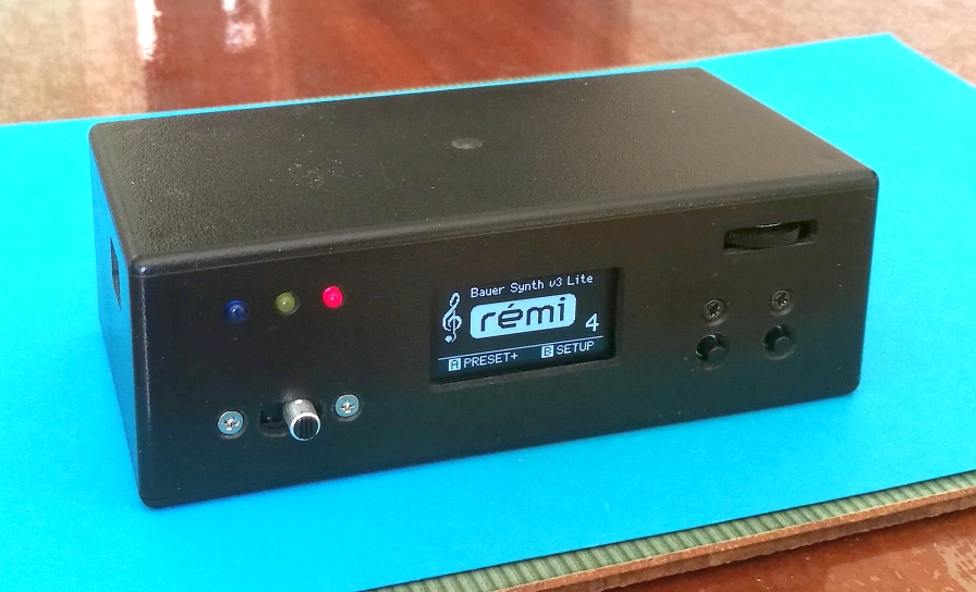
The REMI Synth 'LITE' is battery-powered with OLED display and headphone amp. |
||||
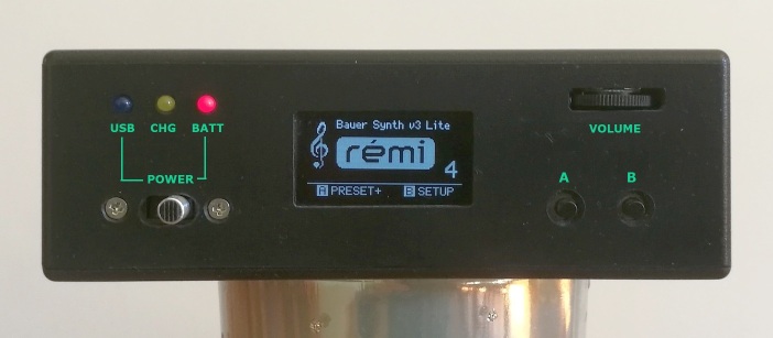
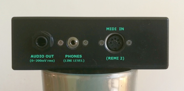
Designed especially as a companion sound module for the REMI 2 handset (MIDI wind controller), this 'Lite' version of the REMI Synth is a more compact battery-powered device using the same "sound engine" software as the other REMI synth models (also based on a PIC32MX MCU). The 'Lite' synth can be attached to the player's belt or pocket with Velcro or a metal clip, allowing more freedom of movement while playing through headphones. A wireless audio transmitter (as used on electric guitars) may be plugged in for cable-free performance with an instrument amplifier. The front-panel user-interface (GUI) is simplified, providing only a few essential day-to-day operations. The GUI comprises a tiny (1.3 inch) OLED display and 2 push-buttons. The back panel provides a MIDI IN socket (DIN-5) with "power-over-MIDI" (5V DC output) to support a REMI 2 handset or any other MIDI controller with a classic MIDI OUT connection. There is a headphone socket (3.5mm TRS jack) and a low-level output (1/4-inch phone jack) for connection to an instrument amplifier. A
USB port provides the same command-line user interface (CLI) as the
other REMI Synth models. The USB connection can supply 5V DC power to
the synth module. It also powers the built-in battery charger.
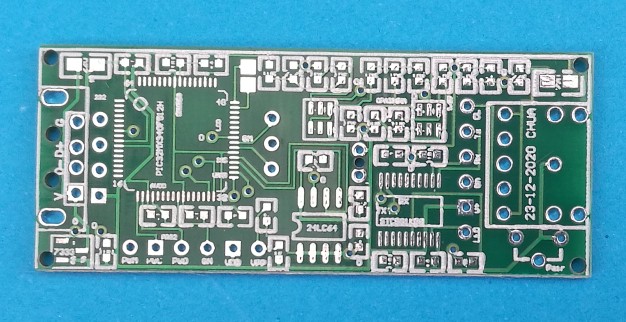
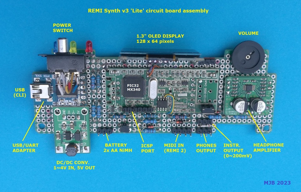
____ The circuit board is built around a PIC32MX340 "audio dongle" designed by a project follower "Chua" who lives in Singapore. Chua's PCB has provision for the I2C EEPROM (24LC08) and PWM audio output components, but access to MCU I/O pins is very limited, so the PCB must be "hacked" to get enough I/O for the synth. For example, a pair of test-point pads (RC13, RC14) are used for the two push-button inputs. The I2C bus signals (SCL, SDA) required for the OLED display are accessed from the EEPROM (pins 5 & 6). The 6-pin ICSP header provides a further two port pins (RB6, RB7) which are used in the battery charging circuit.
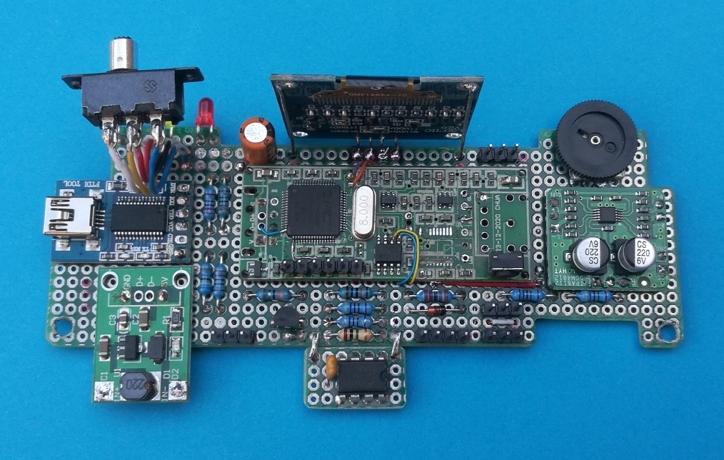
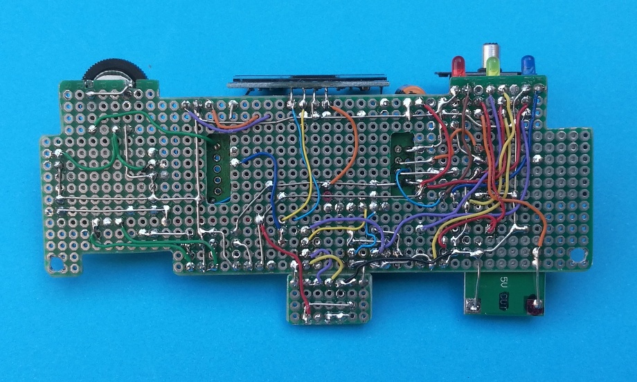
The complete circuit board assembly is shown here...
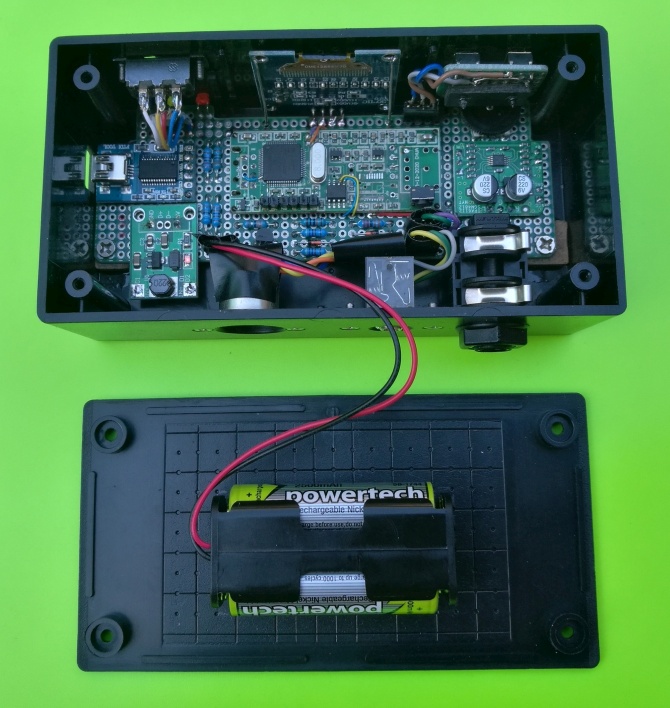
___ The enclosure is a plastic box, size 130 x 65 x 42 mm. This photo shows the internal layout...
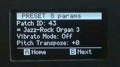
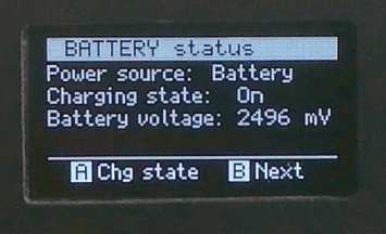
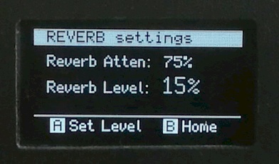
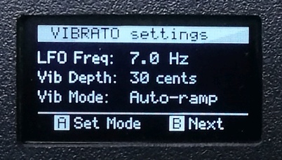
A few of the GUI screens...
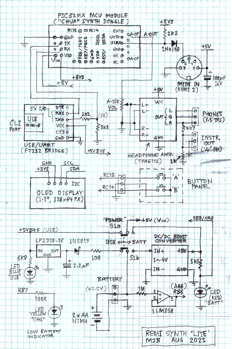
+++ Schematic Diagram
Battery charger operation The synth operates from either USB power or rechargeable battery (2 'AA' size NiMH cells). The battery may be charged using an external fast charger designed for NiMH cells, or using the internal slow "trickle" charger. The internal charge circuit is enabled whenever USB power is applied and the power switch is set to 'USB'. The yellow 'CHG' LED indicates when the battery is at or near full charge, in which case the synth should be operated on battery power. In any case, the battery cannot be damaged by the internal charger because the charge current diminishes as the battery approaches full charge. If the battery voltage falls below the minimum acceptable level, the yellow 'CHG' LED will flash at a rate of 0.5Hz (i.e. once every 2 seconds). It is recommended to leave the synth charging (via a USB power source) if the yellow LED is off (or flashing) while running on battery power. MIDI IN circuit The MIDI IN (receiver) circuit is non-standard. It was designed primarily to accept a REMI 2 (MIDI wind controller). As such, the circuit differs from a standard MIDI IN receiver in two aspects... 1. There is no opto-isolator. This means that a common (GND) connection is required between the MIDI controller and the synthesizer. Pin2 of the DIN-5 MIDI IN socket is used for this purpose.* Ensure pin2 of the MIDI IN DIN-5 socket is wired to GND (pin3), as shown in the schematic. 2. The synth MIDI IN socket also provides 5V DC power to external MIDI devices (controllers). This was implemented primarily to power a REMI 2 wind controller, but may be used to power any MIDI device compatible with the Arduino "Power-over-MIDI" scheme (where DIN-5 pin1 = +5V; pin3 = GND). * Note that many cheap MIDI-USB adaptors also do not have an opto-isolator in their MIDI IN circuits. These devices rely on a common (GND) connection between the adaptor MIDI OUT plug and the synth MIDI-IN socket (DIN-5 pin2). This is contrary to the MIDI standard where pin2 on the MIDI-IN socket should not be connected. However, pin2 of MIDI cable plugs (DIN-5) should be connected to the cable screen. |
||||
|
Send email enquiries, comments, suggestions, etc, to...
See MJB's Index Page ___ ___ |